Wiring diagram, howtos and diy wiki blog with HD images
Home
› 4 Wire Stepper Motor Wiring Diagram : Nema 34 Stepper Motor Specs Wiring Datasheet / The only thing you need to identify is the two pairs of wires which are.
4 Wire Stepper Motor Wiring Diagram : Nema 34 Stepper Motor Specs Wiring Datasheet / The only thing you need to identify is the two pairs of wires which are.
4 Wire Stepper Motor Wiring Diagram : Nema 34 Stepper Motor Specs Wiring Datasheet / The only thing you need to identify is the two pairs of wires which are.. It shows the components of the circuit as simplified forms, as well as the power and also signal links in. The only thing you need to identify is the two pairs of wires which are. Starting from a normal surveillance camera to a complicated cnc okay, so unlike a normal dc motor this one has five wires of all fancy colors coming out of it and why is it so? 4 wire stepper motor wiring diagram. Stepper motor wiring diagram | free wiring diagram assortment of stepper motor wiring diagram.
Preliminary release ezquadhrstepper power section wiring diagram. Difference between 4 wire 6 wire and 8 wire stepper motors. Stepper motors bipolar connections for 2. Effectively read a electrical wiring diagram, one provides to find out how the particular components inside the system operate. About all reprap stepper drivers are bipolar (as opposed to unipolar), so if you're using the standard drivers, you will need a stepper than can be wired as bipolar.
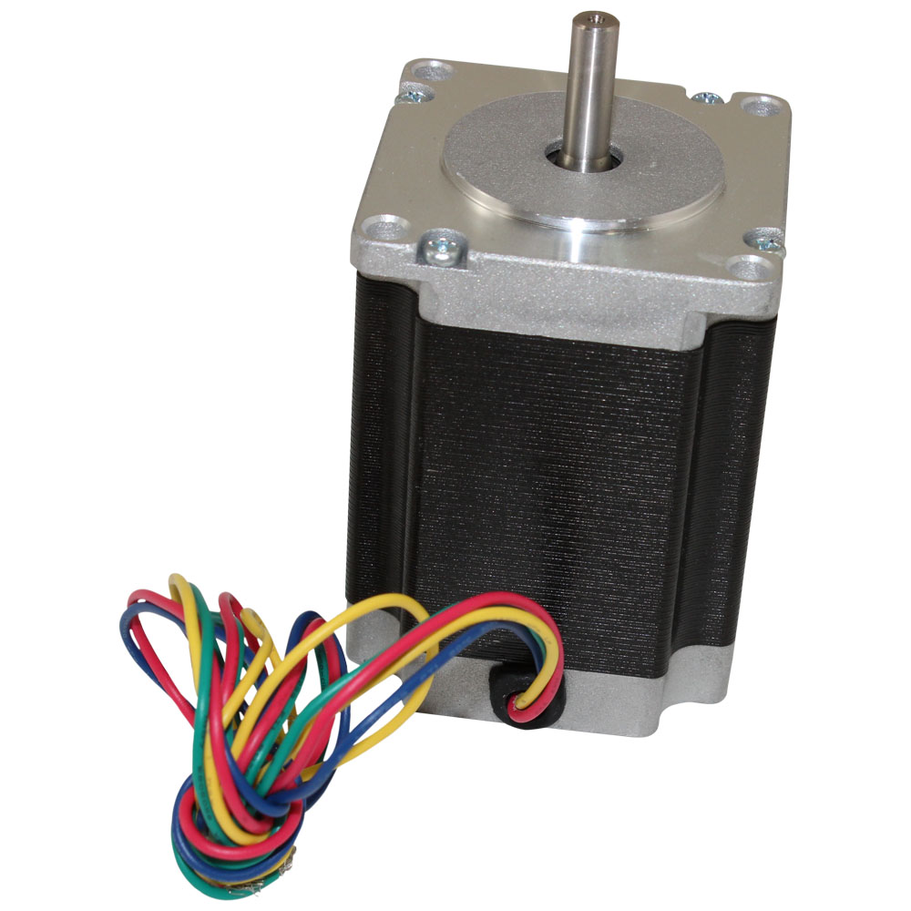
Nema 23 Stepping Motor 24 0 Kg Cm 4 Wire 57bygh310 from www.circuitspecialists.com See below diagrams for how to hook these up. On arduino website, the sample circuit's stepper has 4 wires and is directly connected to a driver ic (a lmxxx), and the. In wiring diagram, it is extremely crucial to have at least one power cord and one connection cable, which are called as stepper motor wiring. If you are planning on building your own 3d printer or a cnc machine, you will need to. Knowledge about 4 wire stepper motor wiring has been submitted by alice ferreira and tagged in this category. Preliminary release ezquadhrstepper power section wiring diagram. Occasionally we may have to slightly change the style colour or even equipment. Attach the arduino board into your computer with an.
Us ship 3axis nema 23 stepper motor 425oz.
In wiring diagram, it is extremely crucial to have at least one power cord and one connection cable, which are called as stepper motor wiring. About all reprap stepper drivers are bipolar (as opposed to unipolar), so if you're using the standard drivers, you will need a stepper than can be wired as bipolar. Us ship 3axis nema 23 stepper motor 425oz. Even so my motor vehicle made a decision or else when it started to randomly choose 4 wire stepper wiring diagram electrical methods that it needed to me tamper with. Attach the arduino board into your computer with an. What is a stepper motor? (four pins) these are the motor connections. Stepper motor wiring diagram from knowledge.ni.com. Preliminary release ezquadhrstepper power section wiring diagram. Interconnecting wire routes may be shown approximately. It shows the components of the circuit as simplified forms, as well as the power and also signal links in. Stepper motors bipolar connections for 2. 4 wire stepper motor has 2 leads in each phase, h bridges with some driving topologies do have static friction effects, but this effect can be reduced by dithering stepper motor signals at higher frequencies.
Stepper motor connection u2013 aansluiten meterkast. Effectively read a electrical wiring diagram, one provides to find out how the particular components inside the system operate. Please note that you should never connect a motor physically directly to an arduino board, unless the board has built in motor drivers. Preliminary release ezquadhrstepper power section wiring diagram. How to wire a stepper motor without a wiring diagram.
Controlling A Stepper Motor With An Arduino Part 2 Azega from www.azega.com (four pins) these are the motor connections. Architectural wiring diagrams play a role the approximate locations and interconnections of receptacles, lighting, and permanent electrical services in a building. Stepper motor wiring diagram from knowledge.ni.com. 3) for motors with 6 wires do not connect the center taps (to anything or each other) 4) for motors with 8 wires the phases can be. If your stepper motor has 4 wires, it is a bipolar stepper motor. All the pictures and circuits of easy tutorials i found on google had 5 wires, (and those with and this is exactly the source of confusion: How to use an arduino stepper motor in ozeki. In wiring diagram, it is extremely crucial to have at least one power cord and one connection cable, which are called as stepper motor wiring.
What we need to realize is that two wires are for.
Unlike unipolar steppers, bipolar steppers have no common center connection. The only thing you need to identify is the two pairs of wires which are. Architectural wiring diagrams play a role the approximate locations and interconnections of receptacles, lighting, and permanent electrical services in a building. It shows the components of the circuit as simplified forms, as well as the power and also signal links in. On arduino website, the sample circuit's stepper has 4 wires and is directly connected to a driver ic (a lmxxx), and the. Stepper motors are dc motors that move in discrete steps. The bipolar stepper motor usually has four wires coming out of it. What is a stepper motor? The wiring diagram/schematic above shows you how to connect the a4899 driver to a stepper motor and the arduino. See below diagrams for how to hook these up. How to use an arduino stepper motor in ozeki. Starting from a normal surveillance camera to a complicated cnc okay, so unlike a normal dc motor this one has five wires of all fancy colors coming out of it and why is it so? Connect the stepper motor to the arduino by following the wiring diagram.
Knowledge about 4 wire stepper motor wiring has been submitted by alice ferreira and tagged in this category. On arduino website, the sample circuit's stepper has 4 wires and is directly connected to a driver ic (a lmxxx), and the. Stepper motor multi controller connection is capable connection steps. They have two independent sets of coils instead. Starting from a normal surveillance camera to a complicated cnc okay, so unlike a normal dc motor this one has five wires of all fancy colors coming out of it and why is it so?
Stepper Motor Basics 4 Wires Bipolar Motor Youtube from i.ytimg.com A wiring diagram is a simplified standard pictorial representation of an electrical circuit. Interconnecting wire routes may be shown approximately. The bipolar stepper motor usually has four wires coming out of it. Starting from a normal surveillance camera to a complicated cnc okay, so unlike a normal dc motor this one has five wires of all fancy colors coming out of it and why is it so? For example , if a module will be powered up and it also sends out a signal of 50 percent the voltage and the technician. Attempted fun with engineering arduino library for. Occasionally we may have to slightly change the style colour or even equipment. Architectural wiring diagrams play a role the approximate locations and interconnections of receptacles, lighting, and permanent electrical services in a building.
Starting from a normal surveillance camera to a complicated cnc okay, so unlike a normal dc motor this one has five wires of all fancy colors coming out of it and why is it so?
Since coils a and b on the diagram above are not connected, the resistance between leads a1 and b1, or between a1 and b2 will be infinite. We do not need to bore us with details such as whether this motor is variably reluctance, permanent magnet or hybrid as that only relates to construction. Preliminary release ezquadhrstepper power section wiring diagram. If you are planning on building your own 3d printer or a cnc machine, you will need to. See below diagrams for how to hook these up. You will need a hardware driver connected between arduino and the motor. The connections are also given i use the following trick to determine how to connect 4 wire bipolar stepper motors: The wiring diagram is generally used in electrical design to intend the positioning of electric circuits. For example , if a module will be powered up and it also sends out a signal of 50 percent the voltage and the technician. On arduino website, the sample circuit's stepper has 4 wires and is directly connected to a driver ic (a lmxxx), and the. You can distinguish them from unipolar steppers by measuring the resistance between the wires. Extending arduino to the laboratory. Or perhaps a wiring diagram for such a stepper.