Wiring diagram, howtos and diy wiki blog with HD images
Home
› Trailer Wire Diagram / How To Wire Lights On A Trailer Wiring Diagrams Instructions / Trailer wiring diagrams trailer wiring connectors various connectors are available from four to seven pins that allow for the transfer of power for the lighting as well as auxiliary functions such as an electric trailer brake controller, backup lights, or a 12v power supply for a winch or interior
Trailer Wire Diagram / How To Wire Lights On A Trailer Wiring Diagrams Instructions / Trailer wiring diagrams trailer wiring connectors various connectors are available from four to seven pins that allow for the transfer of power for the lighting as well as auxiliary functions such as an electric trailer brake controller, backup lights, or a 12v power supply for a winch or interior
Trailer Wire Diagram / How To Wire Lights On A Trailer Wiring Diagrams Instructions / Trailer wiring diagrams trailer wiring connectors various connectors are available from four to seven pins that allow for the transfer of power for the lighting as well as auxiliary functions such as an electric trailer brake controller, backup lights, or a 12v power supply for a winch or interior. Yellow and green are for left and right turns and braking. The white wire is the ground for each light so just hook it to either one of the mounting studs on the back of the lights or to it's own designated ground on the trailer. If your trailer is significantly heavy and is at the upper limits of the towing capacity of the vehicle,. Right turn signal / stop light (green), left turn signal / stop light (yellow), taillight / license / side marker (brown) and a ground (white). 4 way flat molded connectors allow basic hookup for three lighting functions;
Includes 5 and 7 wire plug and trailer wiring schematics. Has separate bulbs for lighting stop and turn signals (both red). 7 pin flat the best! It shows the components of the circuit as simplified shapes, and the capacity and signal friends between the devices. Australian trailer plug and socket wiring diagrams;
7 Pin Trailer Wiring Connector Diagram Forest River Forums from www.forestriverforums.com You must check the trailer manual to see if the wiring is correct, but normally the white wire is called the ground wire, while the brown wire is used for tail lights. If your trailer is significantly heavy and is at the upper limits of the towing capacity of the vehicle,. Trailer wiring diagrams trailer wiring connectors various connectors are available from four to seven pins that allow for the transfer of power for the lighting as well as auxiliary functions such as an electric trailer brake controller, backup lights, or a 12v power supply for a winch or interior trailer lights. Mounted on the left side of the trailer. The 7 pin flat plug will fit into a 12 pin flat socket and work perfectly. Attach white (ground) wire to trailer frame. When shopping for trailer connectors remember that the male end is mounted on the vehicle side and the female on the trailer side. Below is the generic schematic of how the wiring goes.
This car is designed not just to travel one location to another but also to carry heavy loads.
Nov 21, 2018 · 5 wire trailer wiring diagram. 4 pin trailer wiring diagram. Above we have describes the main types of trailer wiring diagrams. Attach white (ground) wire to trailer frame. This is part 3, w. 7 pin flat the best! The 7 pin flat plug will fit into a 12 pin flat socket and work perfectly. Australian trailer plug and socket wiring diagrams. Trailer wiring diagrams 4 way systems. To connect the electric system of your trailer to the vehicle, you will be using special connector. Below we have the wiring diagrams for both a 7 and 13 pin connector. A wiring diagram is an ordinary pictorial depiction of a intricate electrical circuit. As a professional rv transporter i have seen to many trucks wired with those 2 wires to small and cause a fire from overheating.
It is important to note that the white wire is the ground wire, you will notice this even when you buy lights. You must check the trailer manual to see if the wiring is correct, but normally the white wire is called the ground wire, while the brown wire is used for tail lights. Harness installation at the front of trailer, position plug so that harness has some slack when connected to trunk connector. The white wire is the ground for each light so just hook it to either one of the mounting studs on the back of the lights or to it's own designated ground on the trailer. Boat trailer color wiring diagram.
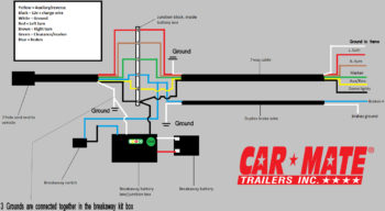
New Breakaway Wiring 2 Car Mate Trailers Inc from carmate-trailers.com A simple closed system while it's never a good idea to dive into a wiring project blind, trailer wiring is actually very simple to work on and troubleshoot. Yellow and green are for left and right turns and braking. Boat trailer color wiring diagram. 4 way flat molded connectors allow basic hookup for three lighting functions; If there is no red or blue wire and there is both a black & a white wire, normally, the black will be brakes and the white ground. It is important to note that the white wire is the ground wire, you will notice this even when you buy lights. Install the yellow/brown wires along the left side of frame. This guide will be talking trailer wiring diagram 5 way.which are the advantages of understanding such understanding?
4 pin trailer wiring diagram.
This article will be discussing triton trailer wiring diagram.which are the advantages of knowing such knowledge? This is part 3, w. A faulty and unsecured ground wire is often the. 4 way flat molded connectors allow basic hookup for three lighting functions; Install the yellow/brown wires along the left side of frame. S trailer brakes blue lt left turn/brake light yellow rt right turn/brake light green a accessory red the most common variances on this diagram will be the (blue/brake) & (red/acc.) wires will be inverted. 11/10 for 2011 wiring diagrams note: Led trailer light kit : The trailer wiring diagrams listed below, should help identify any wiring issues you may have with your trailer. This car is designed not only to travel 1 place to another but also to take heavy loads. It shows the components of the circuit as simplified shapes, and the capacity and signal friends between the devices. Trailer wiring diagrams 4 way systems. Yellow and green are for left and right turns and braking.
4 way flat molded connectors allow basic hookup for three lighting functions; A lot of led lights come with black and white wires and people can easily confuse the black wire for the ground. 11/10 for 2011 wiring diagrams note: All diagrams are as viewed from the cable side This guide will be talking trailer wiring diagram 5 way.which are the advantages of understanding such understanding?
Modifying The M1102 Trailer Wiring For Civilian Use Expedition Supply from www.expedition.supply This diagram shows the colors of a basic trailer wiring setup as well as what each wire is supposed to be connected to. A lot of led lights come with black and white wires and people can easily confuse the black wire for the ground. Trailer wiring diagrams 4 way systems. To connect the electric system of your trailer to the vehicle, you will be using special connector. This is a short video series of the steps that i have taken to refurbish and old utility trailer that was designed and built by my father. 4 pin trailer wiring diagram. The 7 pin flat plug will fit into a 12 pin flat socket and work perfectly. The trailer wiring diagram shows this wire going to all the lights and brakes.
12 pin flat this is an extension of the 7 pin flat.
It is important to note that the white wire is the ground wire, you will notice this even when you buy lights. Trailer wiring diagrams trailer wiring connectors various connectors are available from four to seven pins that allow for the transfer of power for the lighting as well as auxiliary functions such as an electric trailer brake controller, backup lights, or a 12v power supply for a winch or interior Has separate bulbs for lighting stop and turn signals (both red). Australian trailer plug and socket wiring diagrams. The diagrams below show the typical trailer wiring for 4 pin flat connectors all the way to 7 pin round connectors. Use this as a reference when working on your boat trailer wiring. To connect the electric system of your trailer to the vehicle, you will be using special connector. This article will be discussing triton trailer wiring diagram.which are the advantages of knowing such knowledge? Yellow and green are for left and right turns and braking. If your trailer is significantly heavy and is at the upper limits of the towing capacity of the vehicle,. The trailer wiring diagram shows this wire going to all the lights and brakes. The 7 pin flat plug will fit into a 12 pin flat socket and work perfectly. Includes 5 and 7 wire plug and trailer wiring schematics.